
Arduino-based RGB LED strip controller

There are two types of RGB LED strips available in the market:
- RGB strip with addressable RGB LEDs: these types of RGB strips have only three wires for connections (1) +12 V (2) Gnd and (3) DI-Data input
- RGB strip with separate R, G, B inputs: these types of RGB strips have three separate inputs for Red, Green, and Blue colors with one more common input as +12V. So such strips have 4 connections (1) +12 V (2) R – for Red LED (3) G – for Green LED (4) B – for Blue LED
These RGB LED strips can generate almost all the colors and their shades using different combinations of RED – GREEN – BLUE.
Even they can generate different “eye-catching” illuminating effects like multicolor, rainbow, LED chaser, fading, etc.
I bet you all might have seen somewhere the “jaw opening” multicolor led chasing, fading, and animation effect.
Yes or no?
All these are possible using such RGB LED strips.
So do you want to build something like this? Like a multicolor LED chaser, fading, and other animation effects using multicolor LEDs?
What if I say all these you can do with our ARDUINO? Sounds interesting…….?!?!!!???
Yes. You can do all these and play with such RGB strips using ARDUINO, and it’s very easy and simple. So let us start.
- Before directly jumping to the LED strip, first, let us understand the single-cell – the building block of the strip – and that is one RGB LED SMD type
RGB SMD LED
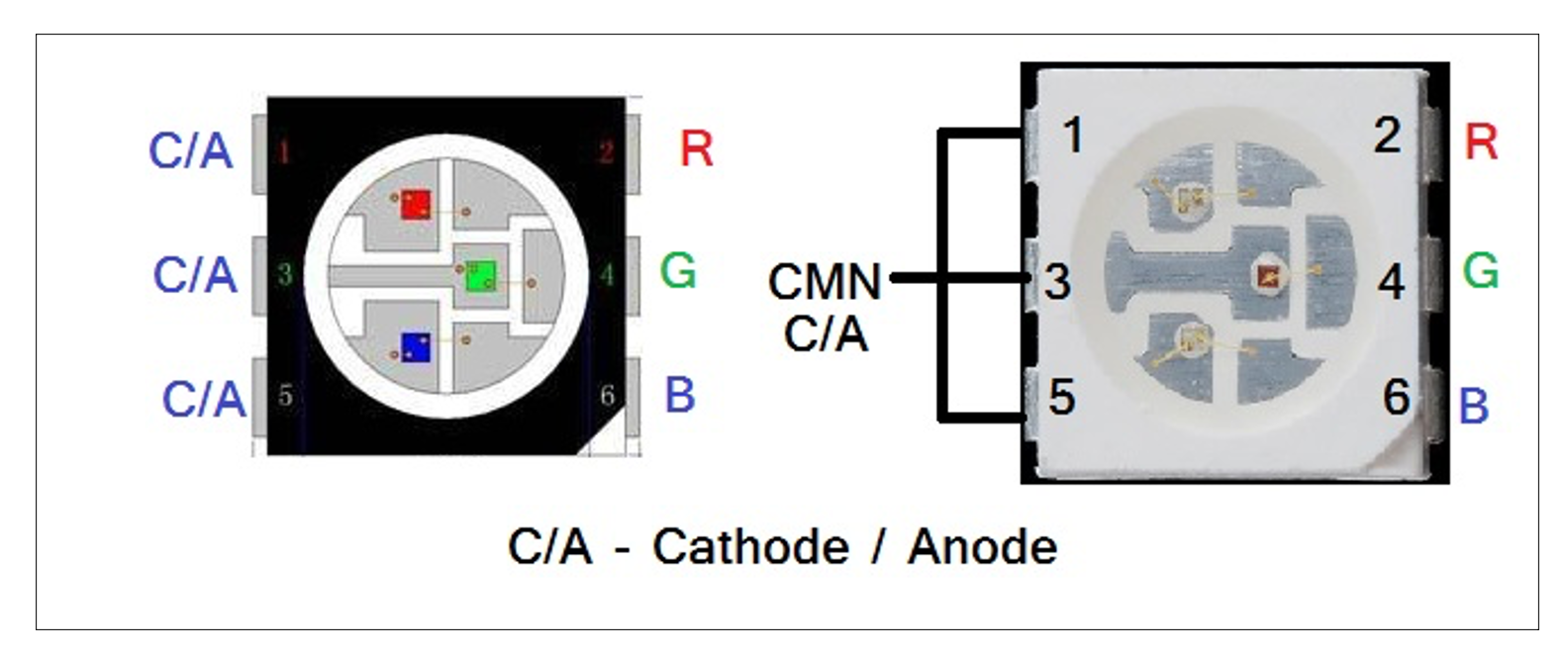 As you can see in the above figure, a single RGB SMD LED is a combination of 3 tiny individual RED, GREEN, and BLUE LEDs. It has 6 terminals. Three terminals are for RED (2), GREEN (4), and BLUE (6) LEDs, while the other 3 terminals are common terminals.
This common terminal can be either anode or cathode, and based on it, there are two types of such LEDs (1) common cathode and (2) common anode. Please have a look at the figure given below.
 It is understood that to turn on any LED in common cathode type RGB SMD LED, we have to apply +Ve supply to R, B, or G terminal, and the common terminal is connected to the ground. While in common anode SMD RGB LED, common terminal is connected with +Ve supply and R, G or B terminal has to be connected to ground.
Now you all might be thinking that there are only 3 LEDs in this, and we can have only 3 colors RED, GREEN, and BLUE. What about other colors? How can we get (generate) all colors from RGB LED?
So here is the logic to generate other colors.
If we turn on two LEDs together, then we have 3 more colors.
RED + GREEN = YELLOW
RED + BLUE = MAGENTA
GREEN+BLUE = CYAN
And if we turn ON all 3 LEDs together, then? Yes, it’s a white color.
But still, 3 + 3 + 1 = 7 colours! What about more colors like PINK, ORANGE, SKYBLUE, LIGHTGREEN, etc.?
To generate other colors, we have to vary the amount of RED, GREEN, and BLUE color because we know the mixing of these three basic colors in different amounts will generate all colors.
So next question is how to vary the amount of these three colors? (It is possible in painting as we can change their amount or dilute them, but here it is not so!)
Here, in our case – the color amount is color intensity – which means the brightness of RED/GREEN/BLUE LED. To generate different colors from RGB LED, we have to vary the intensity (brightness) of RED/GREEN/BLUE LED.
Now, is the picture clear? Got the idea?
To generate different colors in RGB LED, we are going to vary the brightness of RED, GREEN, and BLUE LEDs from 0 to 100%
And we know Arduino can easily vary the brightness of LED! So that’s it……
Arduino has an analog output (PWM output) that will vary LED brightness. Its 3 analog outputs are connected with R, G, and B terminals and change all three LEDs’ brightness.
This much is enough to give you a complete idea. Now let us see how we can control the RGB LED strip using Arduino.
Circuit diagram
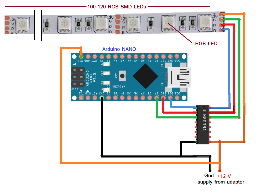 As shown in the figure, the RGB LED strip contains 100 to 120 SMD LEDs. And it requires only two components, Arduino NANO and the current driver chip ULN2003A. The analog outputs D9, D10, and D11 drive G, R, and B inputs of the strip through the current driver chip. The ULN2003A chip is required to provide the required current to the LED strip. The LED strip is a common anode type, so its common terminal is given a +12 V supply. The same 12 V supply is given to the Arduino NANO board and ULN chip also.
Circuit operation
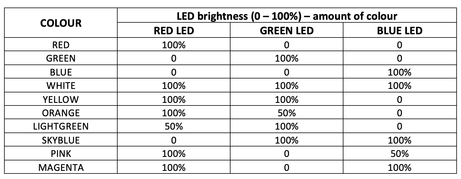
The circuit operation is very simple. The Arduino varies the brightness of all the RGB LEDs by applying PWM output through its D9, D10, and D11 pins. As the PWM output gives 0 to 5 V output, LED brightness varies from 0 to 100% – which means varies the amount of that color from 0 to 100%. See the following table for how different colors are generated by varying LED brightness (color amount)
Software program
We have seen a simple RGB LED strip with individual R, G, and B inputs.
Now let us see another type of RGB LED strip with addressable LEDs. In this strip, also same RGB SMD LED is used as a single cell. Still, it has an inbuilt microcontroller that takes direct data from the host microcontroller (Arduino in our case), illuminates the entire strip, generates different colors, generates chasing and fading effects, etc. In such a strip, it is possible to get a different color of each LED (That was not possible in the previous type. We can get only one color in an entire strip)
So controlling this strip using Arduino will become more interesting.
Getting excited!?!…..
Hold on for a while. Because to program Arduino to control such strip, you need to download its library. But that is on the programming side. Let us first see the circuit diagram and its operation.
Circuit diagram
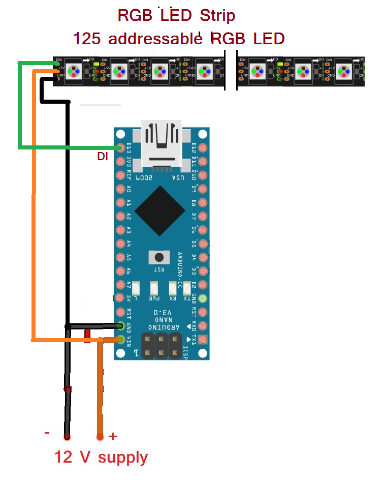 As you all can see, the circuit diagram has become simpler. Now there is no need for the current driver chip. Any digital output pin of Arduino can be directly connected to the LED strip’s DIN (Data Input) pin.
- These LED strips have 3 wire interface (1) 12 V (2) Gnd and (3) DIN
- DIN pin is connected with D13 pin of Arduino directly
- Both Arduino and Strip are given 12 V supply from an adapter (12 V @ 2A)
Circuit operation
As the name suggests, it’s an addressable RGB LED strip – which means all the LEDs have an address. We can turn ON/OFF LEDs, set their color, and vary their brightness by sending data to that address. That means we can set the color and brightness of any individual LED. Actually, we cannot control a single LED but a set of 3 LEDs because one address is assigned to a set of 3 LEDs (in other words, we can say, in such LED strip single-cell consist of 3 SMD RGB LEDs)
So now, it’s time to prepare your Arduino IDE software to make a program for an addressable RGB LED strip.
- You have to download the “FastLED” library from the internet.
- Search for “FastLED library for Arduino” and you can find it easily on Github (or somewhere else)
- Download FastLED zip folder into your Arduino folder (like C:\arduino-1.6.7\libraries)
- Go to your Arduino IDE software, and from the “sketch” menu, go to sketch->include library->add zip library.
- Select the FastLED ZIP folder, and it’s done!
Here I am giving you some sample programs. Try it, test it, modify it and have FUN (isn’t it like “LEARN with FUN”?).
You can also try example programs given along with the library from File->Example->FastLED->…..
In the next article of this series, we shall learn how to operate these RGB Strip using any IR remote and Arduino.
Program 1
Program 2
Program 3