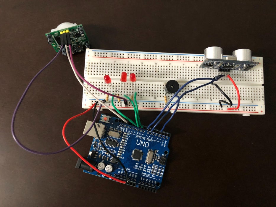
It is a simple tutorial on how to create little a security device using an Arduino.
Supplies
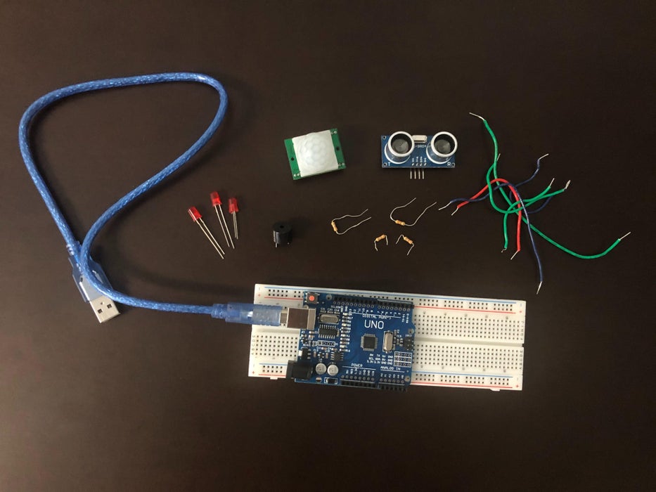
Components and Supplies
Arduino UNO (1)
Breadboard (generic) (1)
Ultrasonic Sensor - HC-SR04 (1)
Buzzer (1)
Pir Sensor (1)
LEDs (3)
Resistor 221 ohm (4)
Wires
Jumper Wires (3)
Step 1: Assemble Materials
Step 6: Setup
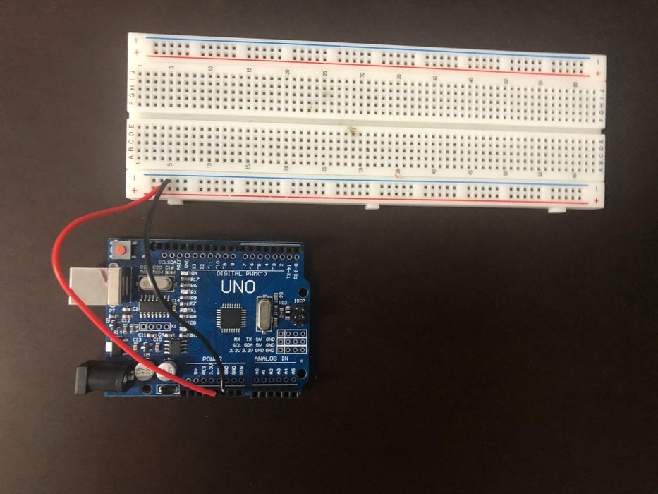
Step 3: Assembly - Breadboard
Firstly, let's connect the 5V and GND pin on the Arduino to the breadboard. Be sure that the wire attached to the 5V pin is connected to the Plus (+) of the breadboard, and the wire attached to the GND pin is connected to the negative (-) of the breadboard.
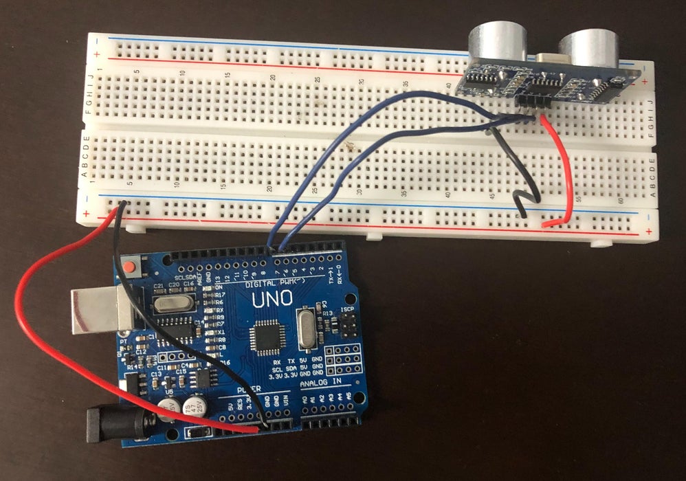
Step 4: Assembly - Ultrasonic Sensor
Time to connect the HC-SRO4 ultrasonic sensor! A great tip is to place the ultrasonic sensor as far right to the breadboard as possible and make sure that it is facing out. Referring back to the setup picture, you should connect the GND pin on the ultrasonic sensor to the negative (-) on the breadboard. Next connect the Trig pin on the sensor to pin 2 on the Arduino and connect the Echo pin on the sensor to pin 3 on the Arduino. Lastly, connect the VCC pin on the ultrasonic sensor to the plus (+) on the breadboard.
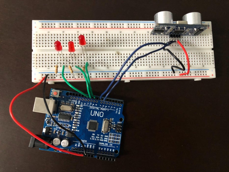
Step 5: Assembly - LEDs
The next step is to connect the LED's to the breadboard and Arduino. Let's first attach the (1 Red LED). So the way to do this, is to connect the anode (the longer leg) to pin 6 on the Arduino with a green wire, and to connect the cathode (the shorter leg) to the negative (-) on the breadboard, using a 220 ohm resistor. Then repeat that step for the (2 Red LED) and then the (3 Red LED), make sure to connect the anode (the longer leg) of the (2 Red LED) to pin 5 on the Arduino and then connect the anode of the (3 Red LED) to pin 6. Once you have done that, your setup should look similar to the picture above.
Step 6: Assembly - Buzzer and Pir Sensor
Buzzer:
This is one of the easiest parts of the whole setup. All that is required to do is to connect the longer leg of the buzzer to pin 7 of the Arduino using a green wire and then connect the shorter leg of the buzzer to the negative (-) of the breadboard using a 220 ohm resistor.
Pir Sensor:
Pir Sensor will have 3 pins and they all need 3 Jumper Wires. Here I will use 3 different colours jumper wires White, Purple, and Pink. all Jumper i will put them in Pir Sensor so White in middle, Purple on left hand side, and Pink on right hand side. after doing that one of the jumper wires will go in Arduino and the other 2 will go in breadboard. white jumper wire will go on Arduino (on GND). On breadboard Purple will go on negative (-) and Pink will go on Plus (+).
Step 7: Code
Attachments


